Got problems? The usual suspects! |
A
common source of annoyance and mystery especially to new owners is how
the air filter cover (dummy fuel tank top) fixes to the petrol tank
filler cap so here are some pics that hopefully will clarify this. There are often pieces missing or they have not been assembled correctly or if your unlucky a previous owner might have chucked the lot! |
The cover clips on to the spring loaded wedges, arrowed red. To release the cover open the fuel cap and push back the levers, arrowed blue. |
With the retaining covers removed the locking wedges, springs and levers in there assembled order can be seen. |
Clutch problems. |
The
hydraulic clutch is well known to cause problems and it’s usually when
the seals in the master cylinder or slave cylinder or both need
replacing. It also doesn’t help if a bike has been stood for a while and the master/slave cylinder has become a bit seized as forcing them can tear the seals. |
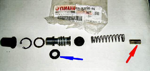 |
These
are the parts you will get in the master cylinder rebuild kit and the
order they fit into the master cylinder, the seal (arrowed blue) must
be fitted onto the piston shown above it the correct way around, check
it when stripped and fit the new seal the same way around, they are a
tight fit to get on the piston when new so use plenty of brake fluid to
lube the seal and piston to help fitting. NOTE: The spring (arrowed red) doesn’t go inside the master cylinder it fits onto the pushrod that fits into the clutch lever. |
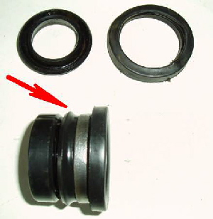
The
clutch slave cylinder rebuild kit only has one seal and one dustcover,
the seal that fits onto the piston must be fitted the correct way
around (arrowed). |
 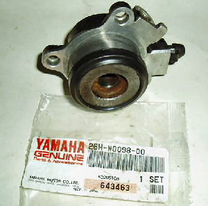 |
This
kit is for a FZ750 part number 26H-W0098-00 the part number may be
different for the Fazer/FZX but the parts are the same, as with many
parts get them for the FZ if the Fazer/FZX is an import to your country
such as the UK |
Many
owners have had real problems bleeding the clutch myself included, but
as i had rebuilt the master cylinder, the slave and fitted a new
braided hose with new sealing washers there didn’t seem to be any
reason why it would not bleed! The reason turned out to be the threaded hole that the bleed nipple screws into in the slave cylinder was worn and when the bleed nipple was tightened up it was still allowing air into the system. When bleeding the system the fluid that is expelled must be replaced with fluid from the reservoir but with the bleed nipple leaking air was being drawn in around it instead of fluid being drawn from the reservoir. The simple and cheap solution to this was to wrap some PTFE tape, (the very thin stuff that plumbers use on pipe threads) around the bleed nipple threads, after doing this and bleeding the system 3-4 times i had a full clutch lever and have had no proplem with it since. If you still can’t bleed it you could try pre-filling the brake line and slave cylinder with fluid then bolt them up and bleed the master cylinder first at the bolt the brake line attaches to it, it might help get it started. |
Fitting LED Indicators. |
I fitted LED indicators using the standard flasher unit and had the usual problem that is “They don’t work”. The
wiring diagram below came with these resistors, now the first thing you
should notice is that one resistor is shown fitted to one indicator so
even if they had worked you would obviously need four of them if you
fitted LED indicators all round, they are not the “universal” solution
as often claimed! |
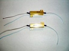 |
These didn’t work and you would need four of them if you fitted LED indicators all round and not two as advertised! |
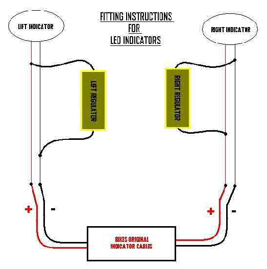 |
This is the wiring diagram that came with the resistors, it didn’t work! |
I
eventually bought a proper electronic flasher unit for use with LED
indicators and it worked, if your fitting LED indicators i recommend
getting one first as last, mine cost £20 but it’s the only thing i
found that worked correctly. I ordered the unit for a yamaha but it does not plug straight into the FZX wiring as the connector is different but it's only two wires (the same as a FZX) and just needs a couple of new connectors fitted. |
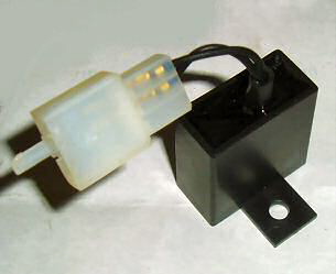 |
It ain’t big but it is clever and it works. |
The
next problem, when i plugged in the dash the indicator warning
light didn’t work and also caused all the indicators to come on at once
like hazard warning lights, very weird! So
finally i put a single LED in parallel on each of the front indicators
and success, a flashing single LED warning light with the indicators. |
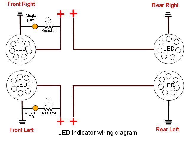 |
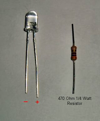
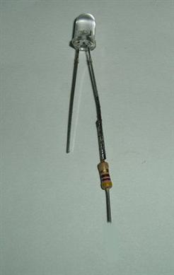
Most
LED's are not designed to run on 12volts but they are available with a
resistor soldered to them so they can or you can solder a resistor on
yourself like i did, a 470-500 Ohm 1/4Watt resistor will do the job. LED’s have a positive and negative connection (anode = positive, cathode = negative) the positive is the longer leg and the connection the resistor should be soldered to. |
  |
Lost the reserve fuel? |
|
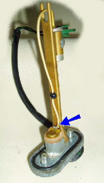
If
you keep running out of fuel because the tank won’t go onto reserve
it’s often because the wire (arrowed) has broken off the fuel sensor
which is located inside the tank. Consider
being in the fast lane and running onto the “simulated” reserve it
unneccesarily places you in a dangerous situation of having to flick
the reserve switch to turn the fuel pump back on and hoping the carbs
fill up with fuel before you start to slow down and have to try and get
into a slower lane hoping that someone doesn’t drive into the back of
you! |
|
NEXT PAGE |
